This article follows steps on how to add Modbus TCP measurement to your terminal setup via Device Manager. If you require help locating your preferred group of devices, please refer to the article Locating your device.
Add measurement
Go to the group that you want to add your measurement into and select the measurement tab on the upper row of the page. After you have selected the measurement tab open, you will see what measurements are added to this group, if at all. On the upper right side of the screen, select the Add measurement + button to add a new measurement.
Note that measurement will be added only to the group you are in and to the subgroups of the current group. For example, should you add measurement to the topmost level, it will be available for all the groups in your organization. These are called inherited measurements. In our example we are adding measurement to a single group at low levels, thus it will only affect only this smaller section.
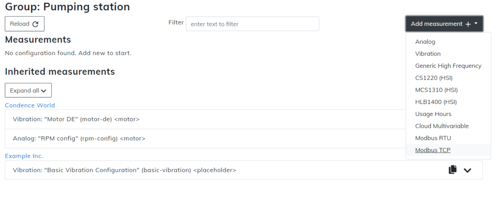
Select Modbus TCP and continue with this document
Modbus configuration
In the measurement configuration window, you are able to configure measurements for your terminal. Without correct measurements, it is possible that nothing will be shown on your user interface or that it will show in a way that is not intended. Carefully see that your metrics are correct.
Please remember, that many of the Modbus configuration values are only covered in the device manual. Refer to your manual for the right values.
Sections with asterisk * are mandatory.
Template can not be changed after you have selected the initial measurement.
Name is what the measurement will be known from here on out. It is recommended to use the name that matches the measurement so it will be easy to recognize.
Key is the unique identification for the measurement. On this level of the hierarchy, the key needs to be unique and can’t overlap with any other. As with the name, it is highly recommended to use the key that matches the intended measurement. Key requires only the use of lower case ASCII letters, digits, and dashes instead of spaces.
Target, unlike Key, can be the same between more than one measurement. Target requires only the use of lower case ASCII letters, digits, and dashes instead of spaces.
Address section needs to have the address your Modbus uses. Only one address can be added to one measurement, so if you have multiple addresses, you need to have multiple measurements also.
Function has you select from two options: Read holding registers (3) and Read input registers (4). Select the one that your device uses and continue. This information should be available in the device manual.
Index number is located in the manual, please refer to it when making the measurement.
Count number is located in the manual, please refer to it when making the measurement.
IPv4 Address is the IPv4 Address that your Modbus device uses.
Port number used in the network configuration should be added here.
Speed is the bits per second (baud) that your measurement will use. Select the right speed from the dropdown menu.
Data bits are either 5, 6, 7 or 8. Choose the right one for your device..
Parity is either none, even or odd.
Stop bits are either 1 or 2.
Sampling interval can be chosen from 1 second up to 1 hour.
Report interval can be chosen from 5 minutes up to 12 hours.
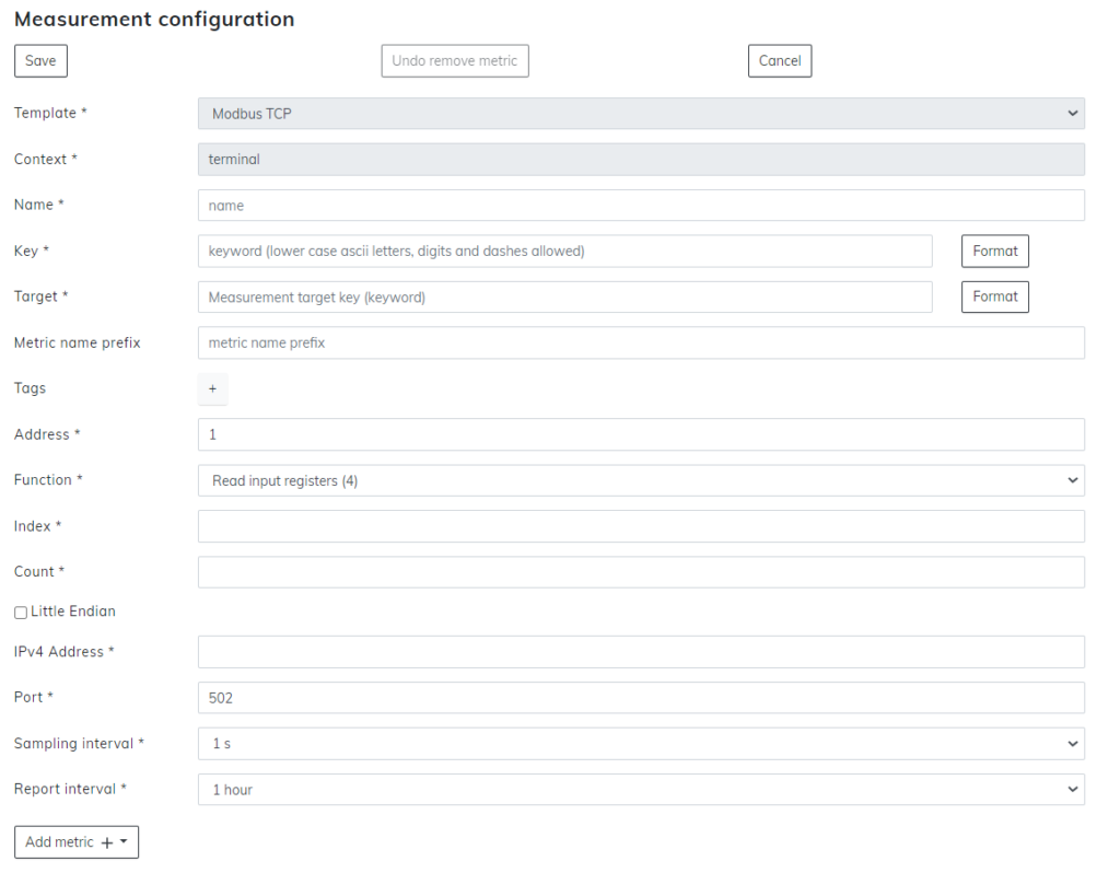
When you have all the previous sections written down, select the Add metric + button from the bottom. This will open up a menu. From this menu select your preferred type of analysis.
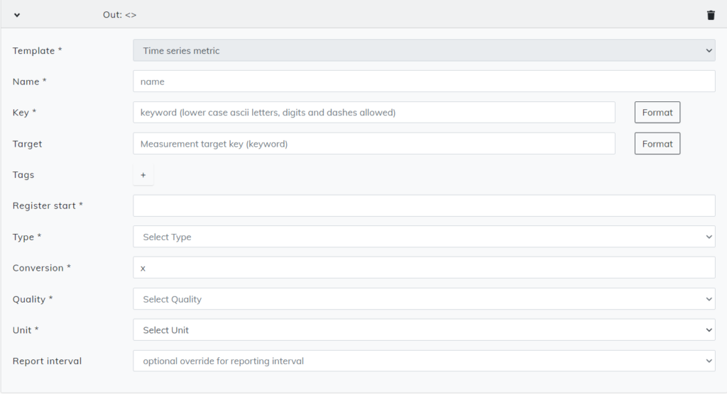
Time series metric
Name of the analysis should match what we are about to analyze, so it will be easy to recognize. Note that the name you choose is the one that will be visible in the user interface later on for this metric.
Key needs to be unique identification for this metric and can’t be used on any other measurement on this hierarchy level.
Register start is the number of bytes this metric uses. Bytes for metrics are covered in the Modbus device manual.
Type lets you choose what is the right bit type for this metric:
- 16-bit integer
- 16-bit unsigned integer
- 32-bit integer
- 32-bit unsigned integer
- 64-bit floating-point number
- Bit
Conversion lets you put your equation for this metric. Use only x if no equation is needed.
Quality has the option to select what you want to measure.
Unit is determined after you have chosen your quality.
State metric
Name of the analysis should match what we are about to analyze, so it will be easy to recognize. Note that the name you choose is the one that will be visible in the user interface later on for this metric.
Key needs to be unique identification for this metric and can’t be used on any other measurement on this hierarchy level.
Register start is the number of bytes this metric uses. Bytes for metrics are covered in the Modbus device manual.
Bit lets you add the correct bit information for the metric.
Unit is selected from 3 options:
- Yes/No
- On/Off
- True/False
For every bit and every metric, you need to do these steps again. Press Add metric + to add additional metrics if needed.
Setup and publish are done exactly the same as with any other measurements. Follow the articles Setups tab & Publishing the setup for additional information.