Generic High Frequency measurement setup follows the same formula as other Vibration measurement configurations.
Measurement configuration
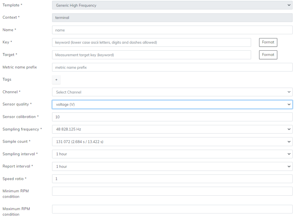
In the measurement configuration window, you are able to configure measurements for your terminal. Without correct measurements, it is possible that nothing will be shown on your user interface or that it will show in a way that is not intended. Carefully see that your metrics are correct.
Sections with an asterisk * are mandatory.
Template can not be changed after you have selected the initial measurement. In this case, we see an option for vibration, as that is what we chose on the previous page. Should you wish to change the template, press cancel and start a new measurement.
Name is what the measurement will be known from here on out. It is recommended to use a name that matches the measurement so it will be easy to recognize.
Key is the unique identification for the measurement. On this level of the hierarchy, the key needs to be unique and can’t overlap with any other. As with the name, it is highly recommended to use the key that matches the intended measurement. Key requires only the use of lowercase ASCII letters, digits, and dashes instead of spaces.
Target, unlike Key, can be the same between more than one measurement. On target, you can write what the sensor will measure. For example, let’s say your sensor is located on the drive-end part of the motor, so your target can be motor-de. Since multiple sensors can be attached to the same part of the machine, so can multiple measurements use the same target here also. Note that these are examples, and your configurations may vary drastically. Target only requires lowercase ASCII letters, digits, and dashes instead of spaces.
Channel lets you choose what sensor of the configuration to use.
Sensor quality section has the option to choose what the sensor will monitor. Options are voltage (V), ampere (A), and micro-strain (FDS).
Sensor calibration is by default 10 and in general, should not be tampered with unless specifically required. Sensor calibrations are measured as millivolts, mV, per square meter as acceleration. Default 10 would be then ten millivolts per square meter of acceleration.
Sampling frequency lets you select an option between a 48k Hz sampling frequency or a slower 9.8k Hz sampling frequency.
Sample count has you select how many samples are taken during each sampling interval. Each option shows two different sets of time intervals. In our example, the sample count is 131 072 with options for 2.584 seconds and 13.422 seconds. To select between the two-time options, you have to change the sampling frequency. The sampling frequency of 48k is the option for the faster sampling speed, and 9.8k is for the slower sampling speed.
Sampling interval is how often the terminal will take the sample from the sensor. This can vary from 5 minutes to 1 hour.
Report interval section lets you choose how often you will receive reports from the sensor to the user interface. Reporting intervals can vary from 5 minutes to 2 hours.
Speed ratio is used if your gears run at different amplitudes and need to adjust their speed ratio. If no adjustment is needed, the speed ratio should be kept as default 1.
RPM source lets you choose where to get RPM measurements.
When you have all the previous sections written down, select the Add metric + button from the bottom. This will open up a menu. From this menu, select your preferred type of analysis.
